SMPTE ST 430-12:2023-09
Revision of SMPTE ST 430-12:2014
SMPTE Standard
D-Cinema Operations — FSK Synchronization Signal
Approved - 2023-09-12
SMPTE (the Society of Motion Picture and Television Engineers) is an internationally-recognized standards developing organization. Headquartered and incorporated in the United States of America, SMPTE has members in over 80 countries on six continents. SMPTE’s Engineering Documents, including Standards, Recommended Practices, and Engineering Guidelines, are prepared by SMPTE’s Technology Committees. Participation in these Committees is open to all with a bona fide interest in their work. SMPTE cooperates closely with other standards-developing organizations, including ISO, IEC and ITU. SMPTE Engineering Documents are drafted in accordance with the rules given in its Standards Operations Manual.
At the time of publication no notice had been received by SMPTE claiming patent rights essential to the implementation of this Engineering Document. However, attention is drawn to the possibility that some of the elements of this document may be the subject of patent rights. SMPTE shall not be held responsible for identifying any or all such patent rights.
This document was prepared by Technology Committee 27C.
This edition updates external references to their latest versions and consolidates Amendment 1:2019.
Copyright © 2024, Society of Motion Picture and Television Engineers. All rights reserved. No part of this material may be reproduced, by any means whatsoever, without the prior written permission of the Society of Motion Picture and Television Engineers.
This clause is entirely informative and does not form an integral part of this Engineering Document.
Synchronization of Digital Cinema assets is typically accomplished within the media block. There are new applications which decode auxiliary data in a device external to the media block. This standard describes a signal that can be used to externally synchronize auxiliary data to a picture track in a Digital Cinema Composition. The signal is designed to be output from the Audio Media Block and relies on a known synchronization between the audio and picture at this point.
This standard describes the modulation and protocol for transmitting a synchronization signal over a digital audio link.
The methods by which the synchronization signal is packaged or generated or used to establish synchronization are outside the scope of this specification.
Normative text is text that describes elements of the design that are indispensable or contains the conformance language keywords: "shall", "should", or "may". Informative text is text that is potentially helpful to the user, but not indispensable, and can be removed, changed, or added editorially without affecting interoperability. Informative text does not contain any conformance keywords.
All text in this document is, by default, normative, except: the Introduction, any clause explicitly labeled as "Informative" or individual paragraphs that start with "Note:"
The keywords "shall" and "shall not" indicate requirements strictly to be followed in order to conform to the document and from which no deviation is permitted.
The keywords, "should" and "should not" indicate that, among several possibilities, one is recommended as particularly suitable, without mentioning or excluding others; or that a certain course of action is preferred but not necessarily required; or that (in the negative form) a certain possibility or course of action is deprecated but not prohibited.
The keywords "may" and "need not" indicate courses of action permissible within the limits of the document.
The keyword "reserved" indicates a provision that is not defined at this time, shall not be used, and may be defined in the future. The keyword "forbidden" indicates "reserved" and in addition indicates that the provision will never be defined in the future.
A conformant implementation according to this document is one that includes all mandatory provisions ("shall") and, if implemented, all recommended provisions ("should") as described. A conformant implementation need not implement optional provisions ("may") and need not implement them as described.
Unless otherwise specified, the order of precedence of the types of normative information in this document shall be as follows: Normative prose shall be the authoritative definition; Tables shall be next; then formal languages; then figures; and then any other language forms.
The following documents are referred to in the text in such a way that some or all of their content constitutes requirements of this document. For dated references, only the edition cited applies. For undated references, the latest edition of the referenced document (including any amendments) applies.
No terms and definitions are listed in this document.
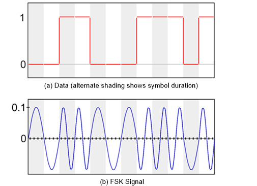
The modulation scheme used to convert digital data to a digital audio signal using Frequency Shift Keying (FSK) is shown in Figure 1. Bits shall be delivered at a constant rate using one symbol per bit. Digital 0 shall be transmitted as a half sine cycle at 6 kHz. A Digital 1 shall be transmitted by a full sine cycle at 12 kHz. The polarity of each symbol shall depend on the previous symbol. This is done to avoid discontinuities in the slope of the modulation signal. For example, the 1st bit in Figure 1, digital zero, is coded using a positive-going half-cycle, while the 11th bit, digital zero, is coded using a negative-going half-cycle.
The modulated audio shall be sampled 4 or 8 times per symbol for 48-kHz and 96-kHz sample rates, respectively. Each symbol shall be sampled symmetrically; i.e., neither the signal peak nor the zero crossing point is a sample point. See Figure 2.
The peak level of the signal is defined to be 0.1 (Full Scale = +/- 1.0). The actual sample values shall be those defined in Figure 2.

NOTE — The stated peak level of the signal value (0.1) is approximate. The actual value will depend on the sample depth.
The following pseudo code describes the order of arrival of information
within the synchronization bit stream. The pseudo code is roughly based on
C language syntax, but simplified for ease of reading. Field elements
contained in the bit stream are designated by a monospaced font. All elements
in the bit stream shall be ordered from MSB to LSB.
| Syntax | Word Size (bits) |
|---|---|
SyncPacket() { |
|
SyncWord |
16 |
EditRate |
4 |
Reserved |
2 |
UUIDSubIndex |
2 |
UUIDSub |
32 |
EditUnitIndex |
24 |
CRC |
16 |
Reserved |
4 |
RemBits |
Variable |
| } /* end of SyncPacket() */ | |
The SyncWord shall be 0x4D56 or 0100 1101 0101
0110.
The EditRate code specifies the edit rate of the picture associated with the auxiliary data. This data is used by the decoder to determine other parameters that are dependent on the edit rate. The EditRate code is specified in Table 2.
| EditRate Code | Edit Rate |
|---|---|
0x0 |
24/1 |
0x1 |
25/1 |
0x2 |
30/1 |
0x3 |
48/1 |
0x4 |
50/1 |
0x5 |
60/1 |
0x6 |
96/1 |
0x7 |
100/1 |
0x8 |
120/1 |
0x9 - 0xF |
RESERVED |
An edit unit may contain multiple synchronization packets as specified in Table 3.
| Edit Rate | Number of Packets |
|---|---|
| 24/1 | 4 |
| 25/1 | 4 |
| 30/1 | 4 |
| 48/1 | 2 |
| 50/1 | 2 |
| 60/1 | 2 |
| 96/1 | 1 |
| 100/1 | 1 |
| 120/1 | 1 |
The UUID shall be divided into 4 successive synchronization packets (see 6.2.3). The time required to obtain the complete UUID is dependent on the edit rate as shown in Table 4.
| Edit Rate | Time Required to Obtain Complete UUID (ms) |
|---|---|
| 24/1 | 41.67 |
| 25/1 | 40 |
| 30/1 | 33.33 |
| 48/1 | 41.67 |
| 50/1 | 40 |
| 60/1 | 33.33 |
| 96/1 | 41.67 |
| 100/1 | 40 |
| 120/1 | 33.33 |
The UUIDSubIndex code specifies which sub portion of the UUID is being transmitted in the current synchronization packet. The UUID, which is a 128-bit number, shall be split across 4 successive synchronization packets. A synchronization packet with a UUIDSubIndex of 0 shall contain the most significant 32 bits of the UUID. A synchronization packet with a UUIDSubIndex of 3 shall contain the least significant bits of the UUID. See Clause 8 for the definition of the UUID value.
The UUIDSubIndex of 0 (zero) shall indicate the beginning of an edit unit for all edit rates.
The UUIDSubindex of 2 shall indicate the beginning of an edit unit for edit rates of 48 fps or higher.
The UUIDSubindex of 1 or 3 shall indicate the beginning of an edit unit for edit rates of 96 fps or higher.
The UUIDSub code is the sub portion of the UUID carried in the current synchronization packet.
The EditUnitIndex code is the Edit Unit index ranging from 0 to 224 – 1.
The CRC code is transmitted after the synchronization information for error detection in the transmission path. The CRC shall include all the bits in the SyncPacket up to and including the EditUnitIndex. The following generator polynomial is used to generate each of the 16-bit CRC words: x16 + x12 + x5 + 1.
The CRC calculation may be implemented by one of several standard techniques. A convenient hardware implementation is a linear feedback shift register (LFSR). An example of an LFSR circuit for the above generator polynomial is shown in Figure 3.

Computing the CRC with the above circuit consists of resetting all registers to zero and then shifting the data bits serially into the circuit in the order in which they appear in the data stream.
The reserved bits are reserved for future use. They shall be set to zero.
The RemBits is a variable number of bits to pad out the packet such that the packets align with edit unit boundaries. The number of bits used in RemBits is dependent on the EditRate code as shown in Table 5. Bits in this field shall be set to zero.
| EditRate Code | Remaining Bits (bits) |
|---|---|
0x0 |
25 |
0x1 |
20 |
0x2 |
0 |
0x3 |
25 |
0x4 |
20 |
0x5 |
0 |
0x6 |
25 |
0x7 |
20 |
0x8 |
0 |
The signal may be generated at the time of packaging or generated at the time of playback. Depending on the point of generation, the signal shall be generated with the following sample and Edit Unit alignment.
The first sample of the SyncWord shall be packaged to align with the first audio sample of the Edit Unit.
The first edit unit of the synchronization signal packaged in the audio track file shall have an EditUnitIndex of 0.
The first sample of the SyncWord shall be generated to align with the first audio sample of the Edit Unit.
The EditUnitIndex of a synchronization signal generated at the media block shall match the Edit Unit of the Main Audio track file being reproduced.
The first generated UUIDSubindex shall have a value of 0.
The UUID value carried in the synchronization signal shall be the UUID associated with the Main Audio track file where the synchronization signal is embedded. If the synchronization signal is generated at playback time, the UUID shall be the UUID of the current Main Audio track file. See SMPTE ST 429-3 for how the UUID is derived from the Package UID of the Main Audio track file.
The following Universal Label (UL), as specified in SMPTE ST 400, identifies audio channels that carry the FSK synchronization signal.
| Kind | Leaf |
|---|---|
| Name | FSK Sync Signal Channel |
| Symbol | FSKSyncSignalChannel |
| Description | Identifies an FSK Sync channel |
| UL | urn:smpte:ul:060e2b34.0401010d.03020110.00000000 |
When an AudioChannelLabelSubDescriptor (as defined in SMPTE ST 377-4) references an audio channel that contains the FSK synchronization signal, the items specified in Table 7 shall be present and set as specified therein. The MCA Tag Symbol Value should be used as the TOKEN associated with the FSK Sync channel when used with additional CPL metadata per SMPTE ST 429-16.
| Item | Value |
|---|---|
| MCA Label Dictionary ID | UL of FSK Sync Signal defined in Clause 9. |
| MCA Tag Symbol | FSKSync |
| MCA Tag Name | FSK Sync |